
G-code for LPBF Research Printers
G-code as an Advantage for Laser Powder Bed Fusion Research Systems
G-code, originally developed as a standardized numerical control (NC) programming language, is extensively utilized to define tool paths and operations for computer numerical control (CNC) machines. Its adoption as the de facto standard for Fused Filament Fabrication (FFF) 3D printers highlights its versatility and widespread acceptance. G-code commands are broadly categorized into three classes: movement, tool selection, and special functions.
Core G-code Commands
- Movement Commands (G0/G1): These commands dictate the motion of machine axes.
G0typically denotes a rapid, non-extrusion move, whileG1specifies a controlled, linear movement, often accompanied by an action such as extrusion in FFF or laser activation in laser-based systems.G0 X10: Moves the X-axis to the 10mm position from the origin.G0 X10 Y15: Moves the X-axis to 10mm and the Y-axis to 15mm from the origin.G1 X20 Y20 E10: Moves the X-axis to 20mm and the Y-axis to 20mm from the origin, while simultaneously performing an action quantified by the ‘E’ parameter (e.g., extruding 10mm of filament in FFF).G1 Z0.1: Translates the Z-axis by 0.1mm, commonly used for layer changes in additive manufacturing.
- Tool Selection Commands (T): These commands allow for the selection of specific tools or configurations. The format is a ‘T’ followed by a non-negative integer.
T0: Selects tool 0.T1: Selects tool 1.T5: Selects tool 5.
G-code Implementation in Laser Powder Bed Fusion (PBF) Systems
In laser-based additive manufacturing systems, particularly for research applications involving powder beds, G-code offers a robust and precise method for controlling the laser’s trajectory and operational parameters. Here, the ‘E’ axis (often used for extrusion in FFF) is repurposed to control the laser’s activation. When the ‘E’ parameter is set to a non-zero value during a G1 movement command, it signals the laser to be active for the duration of that movement.
Furthermore, the “tool” selection (T) commands are strategically employed to define specific laser settings, such as laser power and scan speed. This capability is crucial for research, as it allows for rapid and systematic experimentation with different processing parameters within a single build. For instance:
G-Code
T0           ; Selects tool 0, corresponding to a predefined set of laser parameters (e.g., speed, power)
G1 X15 Y15 E1 ; Moves the laser from its current position to (15,15) with the laser activated using parameters defined by T0.
Illustrative Example: Drawing a Square with Varying Laser Parameters
The following G-code sequence demonstrates the capability to apply distinct laser parameters to different segments of a geometry, a valuable feature for material science research and process optimization. This example draws a 1cm square on the powder bed, applying parameters from T0 for horizontal lines and T1 for vertical lines.
G-Code
T0             ; Set laser parameters for horizontal lines (e.g., Power A, Speed B)
G0 X10 Y10     ; Rapid move to the starting corner of the square (10,10)
G1 X20 Y10 E1  ; Draw the first horizontal line from (10,10) to (20,10) with laser active (T0 settings)

T1             ; Set laser parameters for vertical lines (e.g., Power C, Speed D)
G1 X20 Y20 E1  ; Draw the first vertical line from (20,10) to (20,20) with laser active (T1 settings)

T0             ; Re-select T0 parameters
G1 X10 Y20 E1  ; Draw the second horizontal line from (20,20) to (10,20) with laser active (T0 settings)

T1             ; Re-select T1 parameters
G1 X10 Y10 E1  ; Draw the second vertical line from (10,20) to (10,10) with laser active (T1 settings)
Extended Functionality through G-code Manipulation
The open and textual nature of G-code provides significant advantages for researchers, enabling advanced functionalities beyond what standard slicer software might offer directly. By programmatically modifying or generating G-code, researchers can implement novel processing strategies and explore complex material behaviors. Two notable examples include remelting and customized infill patterns.
Remelting
Remelting is a technique used to enhance the surface quality and density of manufactured parts. It involves a second pass of the laser over the solidified material, typically focusing on the external contours of each layer. While Fused Deposition Modeling (FDM) slicers often allow control over the number of perimeters (or “skins”) and associated toolpaths, implementing remelting in a laser PBF system can be achieved by intelligently manipulating the generated G-code.
Specifically, for each layer (i.e., just before a positive Z-axis increment), the G-code segments corresponding to the external contours (often identified by specific tool changes) can be duplicated. This duplication effectively creates a second pass, allowing the laser to re-melt the designated areas. This approach offers precise control over the remelting strategy without requiring modifications to the core slicing algorithm.
Infill with Custom Patterns
The G-code’s line-by-line structure also facilitates the implementation of custom infill patterns without altering the slicer software. This is particularly useful for investigating how different internal geometries affect mechanical properties or thermal dissipation.
The process typically involves:
- Identifying Infill Lines: The first step is to accurately identify the G-code lines that constitute the infill. In our setup using Cura for metalONE, for instance, Tool 4 (T4) is exclusively designated for infill operations. This allows for straightforward identification of relevant G-code blocks.
- Pattern Generation and Transformation: Once infill lines are identified, a desired pattern of a specific width and height can be programmatically generated. Crucially, since each G-code line defines a segment with an implied direction in the XY plane, this information can be used to correctly orient and rotate the custom pattern to align with the laser’s intended movement direction. This enables the creation of highly specialized internal structures that can be varied layer-by-layer or even within a single layer.
To test our idea we designed this pattern:
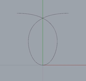
then generated the corresponding G-code and wrote a python script that substituted every occurrence of the movements of the T4 tool with a repetition of our pattern expressed via the correctly rotated G-code.
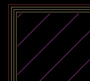
Slicer laser path
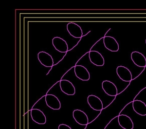
Modified laser path
Conclusion
The inherent flexibility and widespread understanding of G-code make it an exceptionally advantageous language for controlling laser systems in research environments. It provides researchers with fine-grained control over laser paths and processing parameters, facilitating rapid prototyping of experimental designs and in-depth investigations into material-process interactions.